


3.84Kwp REC array using SMA SB4000TL inverter, Asbocking, Suffolk
DC EARTHING
Array earthing (DC)
Not all module and inverter manufacturers work to Class II recommendations. If
however the array frame is earthed, as discussed below, then it is possible to bond the array’s negative to the consumers earthing terminal. Experience however has suggested that this practice can often cause problems with built in protection within inverters. As a result of this, it is recommended that the negative is NOT bonded to earth, and that ClassII cabling is utilised.
Array Frame Earthing
General Principals
Most non UK standards state that the PV array frame should be bonded to the building earth in all cases - "Structural metallic parts of the PV generator shall be directly bonded to the main earthing terminal or bar. The bonding requires a local earth and the use of equipotential bonding conductors …".
UK Standards however are not clear on this point, in that some mention that all ‘exposed conductive parts’ should be bonded to the main earthing terminal, whereas BS7671, the IEE wiring regulations, also state that: “if exposed conductive parts are isolated, or shrouded in non-conducting material, or are
small so that the area of contact with the human body is limited, it is permissible not to earth them.”
If Class II equipment is used, with the use of an isolation transformer, it is considered that there is no specific need to bond the array frame since there would be no fault current return path.
Caution must be taken however if there is a potential to touch a bonded item of
equipment or metalwork and the array frame simultaneously, since the array frame could be floating at some specific voltage. If this risk is high, then consideration to directly bond the array frame to the possible contact point should be made.
The presence of stray capacitance makes this a possible shock hazard, although
installations should be made with the goal of looking to minimise coupling capacitances where possible. It therefore recommended that for installations whereby the inverter is not Class II, and whereby the array frame is not within the equipotential zone, then the array frame should be bonded to the consumers earthing terminal if the DNO permits it, or else to its own earth stake. This ensures that any associated metalwork remains near or close to ‘earth’ potential as the lack of Class II protection introduces a potential shock hazard.
Many factors need consideration regarding the earthing of a PV array structure,
including:
• Exposed metallic parts within the equipotential zone must be bonded to the main earthing terminal (BS7671)
• A PME earth is not, in general, allowed to be taken outside the equipotential zone.
• Good earthing of PV array frames will improve the resistance of the PV system to lightning induced surge damage.
• The optimum earthing system for personal safety may be at odds with the best system with regards to fire prevention.
Equipotential zone
Defining whether a PV array lies within the equipotential zone is a key step. BS7671 (IEE wiring regulations) defines the zone as follows:
Earthed equipotential zone. A zone within which exposed-conductive parts and
extraneous-conductive parts are maintained at substantially the same potential by
bonding, such that, under fault conditions, the differences in potential between
simultaneously accessible exposed- and extraneous-conductive-parts will not cause electric shock.
The key to considering whether an array should be treated as within the equipotential zone is then the phrase simultaneously accessible. This is defined within BS7671 as:
Simultaneously accessible parts. Conductors or conductive parts which can be touched simultaneously by a person, or in locations specifically intended for them, by livestock.
It is this definition of whether an array lies in the equipotential zone, which appears to have caused some confusion. Certain installations are simple to define such as the array mounted high up on a wall, well out of reach. Other situations are more complicated, for example, the same array mounted in easy reach from a window.
Taking a PME earth outside
It is not generally considered safe to take a PME earth outside and it is this that complicates the earthing issue. The safety issue can be best explained by an example:
Consider a person stood in a garden touching a metal structure bonded to the PME earth - in such a case the earth potential at the persons hand (PME earth) and that at their feet (ground) could be considerably different - especially under a loss of neutral supply fault. It is for this reason that a PV array on a house roof is not recommended to be bonded – as a person washing the array from a metal ladder for example (earthed in the ground at its base) could be at a very different potential to that of the array.
This situation becomes much more complicated when the PV frame includes metallic parts that penetrate into the loft space. Such parts could be touched from within the loft - which may be considered to be within the equipotential zone. In such cases, the requirements for equipotential bonding and that of avoiding taking the PME earth outside the zone are in direct contradiction. However, in such cases where an array can be clearly defined as being within the zone, BS7671 bonding requirements must be met, hence bonding of the array frame would be required.
If we put ourselves in the "Ladder against the house" scenario, now considered to be an “inside the equipotential zone", then for fairly high loads or a fault down the LV network, the ladder footing will be at one equipotental, and the array frame will be at a slightly different potential, being connected to the consumers neutral.
If no local PME earth rod is installed, then there clearly has to be a small voltage
difference between these two points. For the houses down the street that have PME earth rods (or are physically quite close to them), the local ground and equipotential that the ladder base is at will be very nearly the same as the consumers earthing terminal, reducing the risk considerably.
Bonding requirements
Where equipotential bonding is required, BS7671 states minimum cross sectional areas for the bonding conductors (see AC earthing). These are referenced to the cross sectional area of the main supply neutral conductor.
BS7671 also states requirements with regards to the clamps used to make connections and also to the inspection and testing of the earth bonding.
Separate earth connection
For an array that is positioned outside of the equipotential zone, a separate earth can be provided. A drive in earth rod should be positioned directly beneath the array and the cable run between the rod and array should be kept as short and as straight as possible.
Equipotential bonding between various parts of the array frame may also be necessary.An earth tester may be subsequently used to measure the earth electrode resistance.
Such a design provides a direct route to ground for any lightning induced surge currents.
Positioning the rod directly beneath the array also has the effect that a person touching the array has the same earth potential at their feet and hand (or hand and base of ladder in the case of a roof mounted array).
When is a separate earth connection necessary
In most cases, where an inverter with the equivalent of Class II separation is used, and earthing is not required for surge protection, the array frame can be left floating. This is the simplest solution, and there is no chance of AC exciting the DC side.
In other cases most, if not all, of the installations for which this guide is intended, will be on PME LV networks. The most practical method will be to bond the array frame to the consumers earthing terminal (which is only uncontroversial if within the equipotential zone) which would generally most easily be achieved from within the loft space. This makes the need for the external electrode redundant as the frame is bonded directly to the consumers terminal and so any static charges, induced voltages or overvoltages via inverter isolation failure are then connected directly to earth.
If the frame or part of it is not within the equipotential zone before such earthing it certainly becomes a part of it afterwards. This may be approved by the local DNO because of the danger represented by the remote possibility of the following occurring at the same time:
• there is a failure of the inverter (if it does not have galvanic separation between AC and DC) so that mains voltage appears on the DC side of the system,
• failure of the isolation, if any, between the frame and DC system,
• someone is touching the frame and some extraneous conductor on the roof at earth potential. (e.g. Aluminium ladder touching the ground).
If the frame is earthed then the AC side overcurrent protection would operate.
However the DNO may not want to bond to the PME earth to avoid this situation, and require a separate earthing rod, because of the possibility that simultaneously with all the above, the company neutral may be lost. In this event, and with the frame connected to the PME earth, it would probably be at a different potential than the aluminium ladder at local earth potential. This is the reason for not taking the PME earth outside the equipotential zone. While it is instructive to speculate on the possibility of all these things occurring at once, the possibility of a hazard occurring like this is extremely remote.
BS6651 is not specific about whether a LPS should be bonded to the consumers earth in the case of a PME system. It says you must consult with the local DNO. Therefore it would appear that some DNOs allow the equipotential zone to be extended to the LPS.
An earth spike intended to operate the AC side protection system will require a far lower resistance to earth than one provided for lightning protection, and this could be difficult to achieve with a single spike.
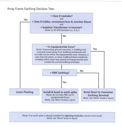
Earthing Decision tree